Wednesday, August 29, 2007

UCB skins, A to B

Build hours: 144
Drill and clecoed the previously fitted B to C skin. Moved the UCB fuselage into the saddle. Cut and fit the A to B skin continously checking the siderails for alignment. Drilled the siderails and clecoed up to bulkhead B.

Tuesday, August 28, 2007

UCB skinning, new B to C skin

Build hours: 136
A new B to C skin was cut, fitted and ready for drilling. The siderails were aligned and leveled with the F bulkhead horizontal stab tabs up to bulkhead A. Looking forward to two skinned Cruisers in formation!

Monday, August 27, 2007

UCB skinning

Build hours: 134
The first 3 skins sections were removed from UCA (sad moment) to be tested as patterns on UCB. The C to D section skins were tight but created an acceptable fit on UCB. After struggling with the B to C skin in an attempt to obtain proper alignment, it was decided to make a new skin using the exisiting skin as a starting point. There will be no pictures of this since this was not a particularly high point in the building process!

Saturday, August 25, 2007

Vertical stab

Build hours: 129
Parts to complete the vertical stab were completed in an earlier post. The E to F skin was notched to accept the vertical stab and the stab was carefully plumbed to the leveled fuselage. The 1" spacing holes were drill in the F bulkhead and the bulkhead was removed. On the bench, the doublers were drilled and clecoed leaving space for the rudder control hinge. This was a good warmup for all of the riveting to come as we calculated rivet lengths, finished head sizes and practiced on a few scraps. After botching about every other rivet on the test pieces, we became adept at rivet removal and boldly moved on to the vertical stab.

The doublers were riveted where possible on the vertical stab and bulkhead. The rudder hinges were then positioned on the stab, underdrilled and reamed to 3/16" for the An3 attachment bolts. The doublers were riveted on and nutplates were installed with 3/32 flush rivets. Again, stopped and admired...


Friday, August 24, 2007

A to B skinning

Build hours: 123
Cut the A to B skin from the pattern and used the ratchet strap to pull it tight while drilling. Trimmed and installed the A to B skin and add the doubler at the A bulkhead. Also, trimmed the siderails square to extend past the A bulkhead by 1". Stopped and admired... Stopped and admired... Stopped and admired...

Wednesday, August 22, 2007

And the skinning still continues...

Build hours: 117
This shows both sides of C to D installed, the C bulkhead bracing removed, and the B to C skin in place. Notice the level. Siderail levelness was checked many times to make sure that no twist in the airframe was being introduced.


C to D skin:
The C to D skin is easier to work in 2 halves. On the large skin, a slight adjustment on one edge can make a big difference in alignment on the other edges.
Plan Note:
The C bulkhead edge has to be notched to allow for the change of angle going forward. The plans do not indicate the number, placement or depth of notches. After looking at the factory skin picture, it appeared to be notched at the bulkhead tabs and again in the center of each tab. The notches need to be 1/2" to 7/16" deep. To shallow and the B to C skin will gap, to deep and the notch bottom will not be covered by the B to C skin.
B To C skin:
Three braces across the beam were used so that ratchet straps could be used to pull up the B to C skin. This allowed the skin to be positioned while remaining tight against the bulkheads, making sure the notches were covered. The joint on the C bulkhead does not lay as tight as the other overlaps so far but is acceptable. (There are several areas on the UC that only another builder would be able to appreciate the workmanship and this is one of them!) Wood strips and spring clamps were used to make sure the compound curve that occurs in the skin on the siderail was not getting out of hand which would cause ripples.


Finally, a saddle was made from the B and D bulkhead for fuselage support as the A to B skin pattern is prepared.

Sunday, August 12, 2007

The skinning continues...

Build hours: 110
The 3/32" clecoes were changed out for 1/8" clecoes and the tail was placed in a saddle so that skinning could continue. Bulkhead "C" was braced so that the edges would remain aligned during the pattern making and skinning process. The poster board pattern was fitted and trimmed for 1/2 of the C-D skin from the bottom stringer to the top stringer. The pattern was found to align correctly on the opposite half and also on both sides of UCB - we must have done something right! The C-D skin will be installed as 2 seperate pieces to reduce waste and make it easier to install. The additional seam will be covered by the turtle deck.
Pictures to follow...

Saturday, August 11, 2007

UCB Skins

Build hours: 105

Skins E-F and D-E along with the E2 bulkhead were completed on UCB. Both skins from UCA were used as templates for UCB.

Thursday, August 9, 2007

E2 Installation

Build hours: 97
After the E-D skin had been fitted and the E-F skin had been fitted and trimmed to the F bulkhead, the E-F skin was removed and a line was drawn 7 11/32" in from the F bulkhead edge. The beam was cut behind E and turned over. Bulkhead E2 was predrilled and then each tab was backdrilled after aligning the line in the tab hole. Tabs on alternate sides of the bulkhead were done until about 3/4's of the tabs were done. Then, one side was left open while the remaining tabs were completed to the center of the bulkhead.


Sunday, August 5, 2007

Skin E-F

Build hours: 91

Skin E-F was layed out and cut from the pattern. The .016 6061 is not very impressive while cutting and I was beginning to wonder if it was really better than the poster board. Anyhow, the wimpy skin was centered and clecoed to the top stringer and pulled together with strapping tape at three locations along the length. The holes were layed out to be centered on the front and rear flanges, drilled 3/32" and clecoed on the top fuselage half. The beam and fuselage was flipped and the skin was drilled and clecoed on the lower half. The .016 skin becomes amazingly stiff when wrapped and should be more resistant to weather than the poster board:)


Shop note:

The shop was 97 degrees and 60 percent humidity. Even with all the fans going and the excitement(?) of the first skin wrap, that temperature and humidity is a drag.Its obvious that the builder was suffering from too much heat (or.. if I only had a heart - The Tins Man's request from the Wizard of Oz)


Plan note:

You will screw yourself if you don't think far enough ahead since the plans nor the kit construction manual lays out a specific order or indicates why what your doing now will be IMPORTANT in the FUTURE! So... For the horizontal stab to be horizontal, the tabs on bulkhead F should be level. Its easy to lose a 1/16" while cutting and trimming the bulkhead. Add a lines width during alignment to the beam and the tabs will not be level when it time to add horz. stab doublers! To be continued and corrected...


Saturday, August 4, 2007

Rudder Hinges

Build hours: 86
The vertical stab and rudder hinges were made from 6061 1/8 square that was available. The hinge length was cut from the square stock and then multiple hinges were cut. After lay out the pilot holes were drilled, the angles were cut and a belt sander was used to finish and round piece.

Friday, August 3, 2007

Vertical Stab,Skin Patterns

Build Hours: 82
The vertical stab blank was cut from .020 6061. The vertical flanges were made in the bending brake and 3" flanging pliers were used to bend the top tab. The vertical stab doublers were cut from 6061 .025 and formed in the brake. The vertical stab hinge doublers were cut and match drilled. This was completed for both UCs.

Plan Note:
The length for the vertical stab does not include the 5/8" tab. The plans could use more detail around the vertical stab. The information is all there but it requires coalescing information from 3 different drawings.
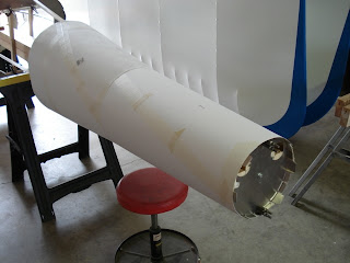

Patterns were made for skin E-F and D-E. The long edge of a sheet of poster board was taped to the lower stringer with 4 1" strips of masking tape and wrapped over the top stringer. Another piece was overlapped on the lower stringer 3/4" taped and again, wrapped over the top stringer. The top overlap was taped with a 2" wide strip of masking tape. The flange edges were marked on the inside of the poster board. The poster board was then removed and trimmed to shape.


Thursday, August 2, 2007

Stringers

Build hours: 76
The stringers for both planes were cut from the end of a sheet of .020 6061 with the Malco snips. Even though a shear would be nice, the big Malco snips make nice clean cuts with relative ease. The layout was done for the flange lines and relief holes were drilled at the corner of the tabs. The blank was loaded into the brake. Bend, flip, and bend again. Duckbill pliers was used to bend the end tabs. A small amount of length adjustment can be made by changing the tab bend. Two holes were drilled on the center line of each bulkhead, top and bottom, at 1/4" and 3/4" from the flange. Each stringer was then centered on the bulkhead and aligned with a wood block to be flush with the flange or tight inside of the flange, drilled and clecoed.

Plan Note:
The plans show a parts layout on the aluminum sheets. I would guess this is the layout used for laser cutting the parts. It is not always practical to follow these layouts if you are scratch building, i.e. - the stringers are made from .020 and are wedged in all around the a-b, and b-c skins that require patterns to be made at a later time. The stringers were cut from the end of the .020 sheet as required.