Saturday, December 22, 2007

Rudder 1

Build hours: 357

Sometimes things workout (see tailcones) and sometimes they don't. The rudder with the rounded leading edge looks great but we slipped up and built a twist into the rudder just like the plans warn. A new spar and ribs have been manufactured and as soon as some new skin material arrives we will replace the rudder and move forward.


Sunday, December 16, 2007

Tailcone

Build hours: 345


Just spent an entire work session forming the tailcone. Four cardboard patterns and 1 aluminum trial and we're still fidgeting with it. We're attempting to create a pinched tailcone instead of the normal "jet exhaust" tailcone.

After taking a break, the final tailcones were made. Here are the pictures of the end result.


The tailcone model or which end is this?


Thursday, December 6, 2007

Elevator hardware

Build hours: 333
Rough skins for the remaining elevators were cut and flat 4130 parts for the elevator and rudder control horns were cut.

Wednesday, December 5, 2007

Elevator construction

Build hours: 332


There is not a layout for the elevators in the plans!?


A rough skin for the elevator, with plenty of excess, was layed out and trimmed from a sheet of 6061 .016. The center line was folded as far as possible in the brake and then moved to two hinged 2"x4"s to complete the bend. An 1/8" wooden dowel was taped into the crease to maintain the bend radius before closing the bend in the 2"x4"s. The ribs were riveted to the top with temporary aluminum rivets then the elevator was flipped and the skin was drilled for the other side of the ribs. The skin was marked at the rib ends returned to the brake again for the hinge flanges. The flanges were temporarily riveted. The elevator was positioned on the stab an the hinge halves were taped to the elevator with strapping tape. The hinge pins were removed and the elevator was drilled for the hinges.


The elevator can be simple to construct as long as you base the construction on the top of the elevator otherwise the angles and taper can get you!


Plan note:

The plans suggest using a shim under the outboard rib of the elevator during construction to avoid building a twist into the elevator. The kit manual mentions building on the top and use some temporary alumium rivets during the construction. The temporary rivets is much easier.


Tuesday, December 4, 2007

Horz stab completion

Build hours: 321

The horizontal stabs are complete. This shows the elevator hinges being aligned with a steel wall stud.


A piece of .062 lexan was used for the 2.5" inspection holes. 6-32 nutplates were riveted to the lexan to secure the inspection plate. By removing 3 screws and loosening the fourth, the inspection plate can be rotated for access to the stab bolts. The lexan covers were installed before closing but could have been rolled and inserted through the hole at a later time.


Friday, November 30, 2007

Horz stab skinning

Build hours: 315

The UCA tail is now hanging from the rafters waiting for the lexan inspection plates to be installed before final closure. The UCB tail is installed and drilled awaiting cleanup, and inspection holes. The UCB tail has taken half the time and a fourth of the struggle to complete since we have the experience from UCA! A few steps in the manual could have made it all a lot more painless. I do not recommend building the tail on the plane but the alternatives suck too.
The clamps pictured below are cheap and easy and greatly simplify the skin installation. Some light spring clamps on the trailing edge will hold until the skin is positioned.


Here are five items to watch for when constructing the tail -
spar level
correct incidence
inboard edge fit
outboard edge square
spar pucker
Check each item and often during the fitting.

Plan note:
The basic steps (which the kit guide doesn't mention, (falls under - should have prior building experience)) are:

1) Mark all flange centerlines before assembling the spars and ribs on the fuselage. Extend the forward spar centerline onto the fuselage and onto the outside of the outboard rib.
2) Install the rough cut skin as pictured and clamp. (Check the 5 items).
3) Use a guide to create the fuselage trim line


4) Remove the skin and trim the fuselage line.

5) Reinstall the skin (Check the 5 items). Mark the ends of the forward spar on the skin. Mark the trailing edge trim line. Mark the outboard rib trim line.

6) Remove the skin. Trim the trailing edge and outboard edge. Mark the spar rivet lines top and bottom, front and rear. Mark the rivet pattern on the inboard rib. Measure and record the distance from the inboard rib rivet to the fuselage and record it on the fuselage.

7) Reinstall the skin (Check the 5 items) . Mark the inboard rib rivet pattern using the recorded distances.

8) Drill and cleco several inboard rib holes top and bottom (Check the 5 items).

9) Push or pull the forward spar to align the flange line and procede to drill every 3rd or 4th hole to the tip (Check the 5 items).

10) Mark and drill the top trailing edge (Check the 5 items) and bottom trailing edge every 3rd or 4th hole. Drill the outboard rib top and bottom and then complete all drilling.

11) Go to bed - you've been at this for a long time!

Wednesday, November 21, 2007

Horz stab skinning

Build hours: 297
The UCA stab only needs inspections holes, cleanup and final riveting. The stab skins have taken a surprising amount of work with a lot of attention to plumb, level, square etc. It is also made more difficult by having to build and skin on the plane which requires a lot of inverted work. The actual steps will be documented on UCB.

Friday, November 16, 2007

Horz. Stab Skins

Build hours: 286
Well, a quick post about stab skins. After installing a stab skin, your are qualified to be a one-armed wallpaper hanger. We have not actually completed a skin yet but here's a quick clip on vacuum forming.


Monday, November 12, 2007

Horzizontal Stab Spar

Build hours: 281
The patient has been moved to a clean room environment for appendage attachment.


Actually, we were getting tired of seeing our breath when working in the unheated shop so a 12x16 enclosure was arranged with a 5400W electric heater so that we can work in comfort through the winter months. Each UC will be positioned through the enclosure as needed. The fuselage has been clamped level across the rails so that the stab can be aligned without worrying about the fuselage moving even though we still do a paranoid check regularly:)
The tail spar was built and bolted to the inboard ribs. The 1x2 is used to stiffen the spar in the fore and aft direction while positioning the outboard rib and preparing for the skin. A prop protractor was set for the -3 degree incidence angle and used to check the angle from the inboard to the outboard end.
Note:
The plans reference the dimension from bulkhead "F" to the rear of the stab spar as 2 3/4". When ours came out to 3 1/4" we were "concerned". A call to the factory confirmed that the 3 1/4" measurement was correct and that the 2 3/4" measurement was based off of the center of the inboard rib rear bolt hole instead of the bulkhead!
Also, an AN-6A bolt was substituted for the AN-7A bolt called for the rear hole on the inboard rib. The AN-7A would have bottomed in the nutplate without too many additional washers.

Thursday, November 8, 2007

Vertical Stab Dorsal Fins

Build hours: 277
Both dorsal fins have been installed. The steps were posterboard pattern, metal template, vaccuum formed radius, particle board form blocks, flanging, shrinking, drilling, deburring, riveting, ADMIRING!
Note:
Some of the rivet stems in our latest batch of Avex rivets have been breaking above the rivet. This may be due to the thinner materials being riveted or inconsistency in the Avex "non-structural" rivets. Either way, when the stem breaks above the rivet, the formed head is opened like flower petals. In the tail area, this has been happening approx. 1 out of every 30 rivets requiring the rivet to be removed and replaced.

After the dorsal fin high, we moved on to kitting the horizontal stab. The outboard ribs were shaped over form blocks with a small amount of shrinking work and all of the spar components were formed up in the break.

Friday, November 2, 2007

More formation flying

Build hours: Who cares!

Coming:)


Going :)

Thursday, November 1, 2007

Vertical stabs completed

Build hours: 272
The top rib and forward spar were positioned. The lightening holes were left out because the weight removed is negligible (see weight calc below), stiffening is minimal and warping during flanging is almost guaranteed!
Weight calc = Holes * pi * radius^2 * thickness * lb/in^3
lbs = 14 * 3.14 * .75 * .75 * .016 * .1
lbs = .04
ounces = .63!

Top rib installed.
Here the skin is clecoed into position for the final riveting. The skin was vacuum formed instead of "carpet formed" as described by Bill Spring and Morry. We hated to break tradition but after seeing the Sonex guys form their wing leading edges on YouTube?? we had to try it. A short video clip will be added later when the horizontal stab skins are made but we had so much fun forming the vertical stab skins that we couldn't stop:)!
The process was - make a rough pattern from poster board, cut out a skin blank, tape the rear edges together, wrap with 4mil plastic, seal one end and stick the shop vac hose in the other and seal. Finally, hit the switch, and before you can say oh crap, the skin is formed and ready for fitting. The process is easy and repeatable.
Notes:
1) Cut your skins with the grain running in the same direction. The skin is stiffer and will form a different leading edge across the grain than with the grain.
2) The empennage skins do not require a mandrel since the skin stiffness stops the bend with a nice radius.
3) Clamp the skin on the vertical stab spar as plumb and true as possible checking alignment from every angle possible! Then, mark a line approx. 1/8" up on the bottom edge with a guide against the fuselage (just like Norm would do on This Old House:)). This will give the skin a good fit with the least amount of effort.


And here is the final product. The top rib has not been riveted so that the refuge from installation of the dorsal fin (coming next) can be dumped.


Saturday, October 27, 2007

Bottom rails, vertical stab

Build hours: 262
The bottom rails were drilled, deburred and riveted to the fuselage bottom. The area around the spar was left open until the actual spar bolt locations were drilled.

Many of the empennage parts had been precut in between other building task and were ready for forming. The obligatory particle board form blocks were cut, smoothed, rounded, etc and the rib were carefully formed. Of course, with the curved flanges, the parts came out of the forms with ripples in the flanges and curved like a banana :( It was finally time to use the shrinker. A few soft presses straightened the part and we drilled and clecoed the ribs to UCA and UCB.

Friday, October 26, 2007

"A" Bulkhead stiffeners

Build hours: 252
The "A" bulkhead stiffener was added. The bulkhead tabs were drilled, the stiffener clamped and then backdrilled 3/32". The holes were then drilled with a 1/8" drill instead of a #30 in preparation for dimpling. The holes were deburred and dimpled and then the stiffener was riveted on. The stiffener was placed so that 1/4" turn fasteners could be installed in the front edge in their streamlined position and #6 nutplates could be installed in the rear edge.

Monday, October 22, 2007

Engine compartment completed

Build hours: 244

Both engine compartments are riveted up and ready for the engine cover. The lower engine baffle and braces are under the skin for a smoother look. The nose cowl hole and slot is flanged and the engine cover will lay flush on the nose cowl ledge. The nose cowl will not be riveted until the engine can be test fit and the oil cooler baffle can be installed. Plan note:Our next step is to flush rivet every other hole on the side rails back to bulkhead "B" and add the angles to the bottom of the fuselage before retiring to some tail work!

Plan note:

We intended to flush rivet every other rivet on the siderails between bulkhead "A" and "B" per the plans. The plans do not mention the need to countersink the rail holes so that the skin can be dimpled for the flush rivets which would need to be done before installing the rail! (The catchall plan note is - prior building experience is required!) With only the rivets in the C to D skin needing removal, we could have accomplished the countersinking. However, a call to the factory suggested using the universal head rivets and then relieving the tank cover skin for those rivets. This is simpler and allows the entire rail to have a 1" rivet pattern showing.




Sunday, October 7, 2007

Engine compartment

Build hours: 230
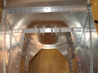
Disassembled, deburred and reassembled both engine compartments. (The deburring fingers are now experiencing a minor numbness!) The front cowls need to be formed and the engine compartments will be ready for riveting! The next view of the engine compartment will be less prickly.

Saturday, October 6, 2007

Engine compartment

Build hours: 224
The front cowl needs a hole for the engine thingy to go through and a few air holes to keep the engine thingy cool. A hole is not complete without a flange so after some masterful routing and a mess of particle board dust in the shop these dies were created for flanging.


The first hole and slot in the test cowl was done by hand with the Morry stick method (labor intensive) and the last slot was made with the die with a few whacks from the deadblow.


Friday, October 5, 2007

Engine compartment

Build hours: 218
Job and scheduling interfered with the important things of life but we are back and moving on the engine compartment. The side braces were added to both UCs.

A joggle was added at the upper end to stop the skin from being pulled in at the firewall.
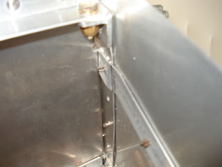
The cowls were formed and mounted along with the lower firewall braces and the the lower engine baffle. The lower baffle and the firewall braces were put under the skin to create a cleaner look around the engine compartment. The oil cooler baffle has been formed but will go in after the engine is fitted.


Tuesday, September 25, 2007

Engine compartment

Build hours: 210
Completed engine compartment on UCA to same point as UCB. Planned engine cowl and baffling arrangement since we are departing from the plans a bit in this area.

Monday, September 24, 2007

Engine compartment

Build hours: 206
The filler pieces and skins for UCB were drilled and clecoed to the engine mounts. The skins were cut to their final dimensions and the double row of rivets and rivet pattern on the A to B skin was laid out. The skins for UCA were also hung for fitting to the engine mount.
A test was made on the front engine cowl to create a more finished look and appears to be workable. A 3/16" flange was added to the node cowl behind the spinner. This will cover the top of the slots in the attached flange and also give the engine cowl an edge to butt up against instead of being an overlap.

Tuesday, September 18, 2007

Engine compartment

Build hours: 198

Jake, the shop rat, caught in the flash!
Anyhow, we riveted the top angle to bulkhead "A". Riveted the engine supports together and to the lower angle on "A" but did not rivet the lower angle to "A". We're planning to align, drill and rivet the engine skins before riveting the lower angle and supports to "A" so that blind rivets are not needed below the engine mount at the "A" bulkhead. This also means we have to order the nuts and bolts that become inaccessible after closure. Two additional changes are also being considered, see below. Installed the engine nutplates and mounted a plywood engine pattern to hold the mount square while fitting the skins.


Change 1 - Make the filler plates in two pieces. One piece rivets to the skin, the other rivets to the vertical engine support then the two pieces are riveted together when adding the engine ring.

Follow up: Decided to stick with the plan filler pieces and use blind rivets as needed.

Change 2 - Speaking of the engine ring... After looking at various examples of the engine ring implementation, we decided to purchase a real metal shrinker(Porto-Metal, I believe) and shrink the flange around the top of the ring. We needed the shrinker for the ribs anyhow to avoid fluting so why not!

Follow up: Fluting and hand skrinking aluminum in the T6 state is only practical for large radii and the metal shrinker must be used sparingly to avoid marking the material to much!

Engine compartment and tail components

Build hours: 194

While waiting for some materials and our work schedule to synchronize, 10 hours was expended in cutting out blanks for the tail parts for both UCs. (horz. stabs, horz. stab forward spars, vertical stab forward spars, rudder spars and ribs) Additionally, the horizontal and vertical engine mounts were cut and flanged to the indicated angles and the "A" firewall angles were aligned and clecoed on.


When Rick and I got back together we were able to drill and cleco the engine mounts together and hang them on the firewall. The mounts were squared by clamping a wood spreader to the front and an engine compartment skin pattern was made. The engine mounts will be leveled when the skin is attached. Finally, all holes EXCEPT the firewall holes that hold the rudder bar attachment were drilled to 1/8".


We also gave metal shrinking a try on the filler plates for the front of the engine mounts. We flanged the straight edge of the filler plate in the brake and made a particle board form with a slot to accomodate the flange to tap the curved edge around. We bent the curved edge to leave 3 puckers. A wood block was clamped to each side of a pucker and the pucker was then flattened. The filler plate came out well but this method is not practical when a tight clamp cannot be applied to both sides of the pucker.

Wednesday, September 12, 2007

Shoudler strap doubler

Build hours: 178


The shoulder strap attach brackets on top of the C bulkhead were added. The skin was trimmed to allow the plates to align with the bulkhead. The plate and doubler were given a mild radius to lay flat across the C to D skin seam since we attached the C to D skin in two pieces. We used driven rivets in this area - because we like to drive rivets. (If you choose to drive the rivets, be sure to wear hearing protection when you stick your head in the fuselage to buck the rivets:)) The doubler plate was attached with flush rivets so that any future bracket would not be hitting rivet heads.

Saturday, September 8, 2007

UCB riveted

Build hours: 174
Assembled and riveted UCB to the same point as UCA. Removed beam. The fuselages look great setting side by side!

Thursday, September 6, 2007

UCB skin prep for riveting

Build hours: 167
Clean and deburred bulkheads and skins.

Wednesday, September 5, 2007

UCB drilled

Build hours: 165
Installed all skins on UCB and drilled up to 1/8". Removed all skins for cleaning and deburring. Moved bulkhead D supports to opposite side of bulkhead and removed beam beyond bulkhead D for easier removal later.

Tuesday, September 4, 2007

UCA riveted

Build hours: 162
In a fit of progress, the remaining UCA skins were drilled up to 1/8" where possible, removed, deburred, clean and reinstalled. Rivets were installed and the beam was extracted leaving the following results: